Sasa!
Last time I left you with all the items ready to be assembled: case, PCBs, components and electronics. Well, with enough foresight I can tell you that I bought some in excess (luckily), as I was convinced that I would surely put them to use.
Despite following the instructions slavishly , I botched a couple of steps, which shortly turned into a spiral of destruction and despair. Hopefully my experience will help you to avoid the same mistakes I made.
I was already aware that this build would take several hours. In these cases, set your playlist in advance and brew yourself a hearty cup of coffee, you are gonna need it sooner than you think.

With the critical priorities sorted, the first step the official guide suggests flashing the QMK firmware onto the 2 Arduino boards. I had already installed the QMK toolchain, so I just plugged the first board, compiled the firmware and…with a cryptic error, avrdude decided to ditch me:
Waiting for USB serial port - reset your controller now (Ctrl+C to cancel)……………. Device /dev/ttyACM0 has appeared; assuming it is the controller. Waiting for /dev/ttyACM0 to become writable.
Connecting to programmer: .avrdude: butterfly_recv(): programmer is not responding
avrdude: butterfly_recv(): programmer is not responding
avrdude: butterfly_recv(): programmer is not responding
avrdude: butterfly_recv(): programmer is not responding
avrdude: butterfly_recv(): programmer is not responding
avrdude: butterfly_recv(): programmer is not responding
Found programmer: Id = ""; type = �
    Software Version = �.; Hardware Version = �.
avrdude: butterfly_recv(): programmer is not responding
avrdude: butterfly_recv(): programmer is not responding
avrdude: error: buffered memory access not supported. Maybe it isn't
a butterfly/AVR109 but a AVR910 device?
avrdude: initialization failed, rc=-1
        Double check connections and try again, or use -F to override
        this check.

avrdude: butterfly_recv(): programmer is not responding
avrdude: error: programmer did not respond to command: leave prog mode
avrdude: butterfly_recv(): programmer is not responding
avrdude: error: programmer did not respond to command: exit bootloader
First thought: since I’m using the USB-C version of the micro-controller, it might not be supported. I’ve opened the config.h file, changed the compiler, tried several options, flashed, changed a couple of things, reinstalled the toolchain, deactivated all the services that might have hindered the serial communication, flashed again and again, but nothing.
After spending almost 2 hours doing this back and forth, I figured out my mistake: when I was asked to reset the board, I pulled the cable out and plugged it back in, in order for avrdude to find the port the board was connected to. Apparently this does not remove the write protection on the EEPROM. I just took the rheophore of a resistor I had laying around on my desk and shorted the GND and RST pin on my board, when prompted to reset. It worked like a charm!
QMK Firmware 0.16.9
Making redox/rev1 with keymap default and target avrdude

avr-gcc (GCC) 5.4.0
Copyright (C) 2015 Free Software Foundation, Inc.
This is free software; see the source for copying conditions.  There is NO
warranty; not even for MERCHANTABILITY or FITNESS FOR A PARTICULAR PURPOSE.

Size before:
text	   data	    bss	    dec	    hex	filename
    0	  25208	      0	  25208	   6278	redox_rev1_default.hex

Compiling: quantum/command.c                                                                        [OK]
Linking: .build/redox_rev1_default.elf                                                              [OK]
Creating load file for flashing: .build/redox_rev1_default.hex                                      [OK]
Copying redox_rev1_default.hex to qmk_firmware folder                                               [OK]
Checking file size of redox_rev1_default.hex                                                        [OK]
* The firmware size is fine - 25208/28672 (87%, 3464 bytes free)
Waiting for USB serial port - reset your controller now (Ctrl+C to cancel).............
Device /dev/ttyACM0 has appeared; assuming it is the controller.
Waiting for /dev/ttyACM0 to become writable.

Connecting to programmer: .
Found programmer: Id = "CATERIN"; type = S
    Software Version = 1.0; No Hardware Version given.
Programmer supports auto addr increment.
Programmer supports buffered memory access with buffersize=128 bytes.

Programmer supports the following devices:
    Device code: 0x44

avrdude: AVR device initialized and ready to accept instructions

Reading | ################################################## | 100% 0.00s

avrdude: Device signature = 0x1e9587 (probably m32u4)
avrdude: NOTE: "flash" memory has been specified, an erase cycle will be performed
        To disable this feature, specify the -D option.
avrdude: erasing chip
avrdude: reading input file ".build/redox_rev1_default.hex"
avrdude: input file .build/redox_rev1_default.hex auto detected as Intel Hex
avrdude: writing flash (25208 bytes):

Writing | ################################################## | 100% 1.95s

avrdude: 25208 bytes of flash written
avrdude: verifying flash memory against .build/redox_rev1_default.hex:
avrdude: load data flash data from input file .build/redox_rev1_default.hex:
avrdude: input file .build/redox_rev1_default.hex auto detected as Intel Hex
avrdude: input file .build/redox_rev1_default.hex contains 25208 bytes
avrdude: reading on-chip flash data:

Reading | ################################################## | 100% 0.19s

avrdude: verifying ...
avrdude: 25208 bytes of flash verified

avrdude: safemode: Fuses OK (E:FB, H:D8, L:FF)

avrdude done.  Thank you.
Lesson learned. Reset means RESET!
I flashed the boards, checked that all was good and moved on.
Then I bent all the 70 diodes and put them on the PCBs. Having applied some masking tape to keep the diodes in place, I flipped the boards. I then applied a generous dose of flux on every soldering point and soldered them on the PCBs. Quickly, I proceeded with the momentary switches, the PJ-320A and the RGB headers.


Adhering to the guide I proceeded to assemble the WS2812. I cut 2 of them and checked the fit on the case. I trimmed a couple of dupont cables, applied the necessary soldering and placed the 2 leds. Here, however, I applied an old trick by the book. On the left side led I put a 330Ω resistor between the header and the DIN, giving the WS2812 some sort of protection.


Finally time for the switches arrived! I created a nerdy 3-layers sandwich: switches, front plate and PCB. A touch of flux and 150 solderings later, I had something that resembled a keyboard.

I then soldered the micro-controller headers and this was the first huge mistake I made: I soldered the boards without having a check first. The case would not close! On the left side the fix was quick and easy since all I had to do was trim the headers and change a tenting kit screw with a shorter one. The right side was painful. I had to de-solder the board, de-solder the header, solder some of the diode’s legs, trim, TRIPLE CHECK and solder the board back. That was quite a task!
When I thought that the pain was over, I plugged in the keyboard and as I was conducting some tests, I noticed that an entire row of the keyboard was not working at all.
Now, one of the trickiest things with electronics and circuitry is the debugging process: it’s not as simple as debugging some code. You have to go through the whole board, test each component and hope to find the culprit quickly. With a multimeter I checked the diodes and the switches, all seemed to be ok. I checked the kiCAD file and manually shorted the corresponding pin to simulate a key-press and there was life. Luckily the board was not the problem.
The only thing left to check was the PCB: with a piece of wire I bypassed that section of the PCB. Well, it worked! My second huge mistake was made while de-soldering the board. Apparently I had damaged a PCB track by scratching it with the tip of my soldering pen.
I took a deep breath and had to make a decision: do I fix the track with a flying wire or use the extra PCB I had?
Of course I chose to use the extra PCB! What’s the point in cutting corners when doing something for yourself, moreover as a hobby?
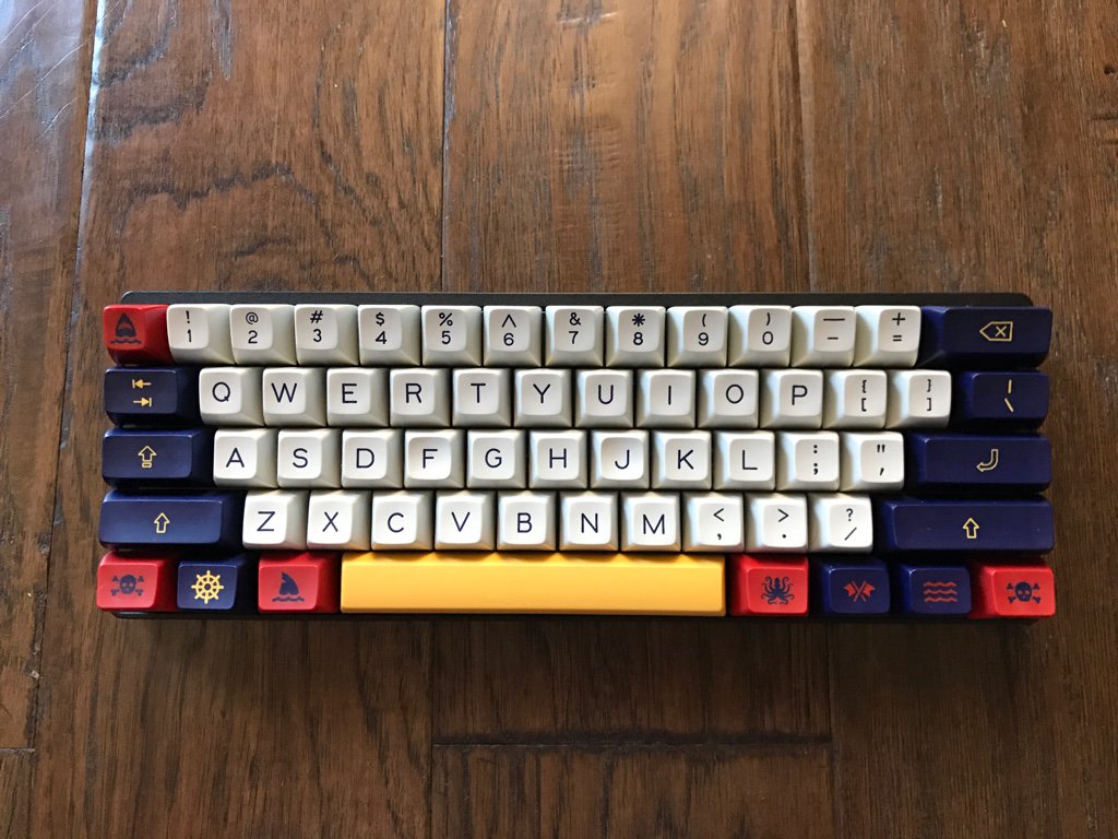
So I salvaged the switches and the board and soldered everything on the fresh PCB. A Few hours and a few hundreds of soldering later and the keyboard was ready! I plugged it in and BOOM, it worked! So, I dressed it with my handmade keycaps, vaguely inspired by the Nantucket Selectric set and took this pic:

In the next post I’ll show you how I customized the firmware, in order to add the layer detection and show it on the LED.
Till then, stay tuned! ⚒