Sasa
2023 was a year of joy, and there is no joy without builds! After experimenting with self-hosting, NAS, and video surveillance, I decided to revamp my tools of the trade and give a companion to my Redox Scenic, integrating all the missing features. Here I proudly present the Ampere Pad v1!
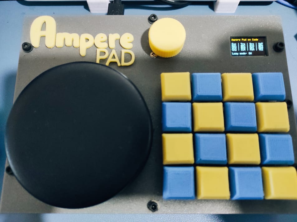
It is a feature-rich handwired 4x4 macropad, integrating 2 rotary encoders, a 0.96-inch OLED display, and a speaker (because we all love some 8-bit pleasure).
The Ampere Pad is powered by an Arduino Pro Micro, in its Elite C variant, with QMK Firmware.
The build took a long time; it was painful, and failures were constantly behind the corner. But luckily, my perseverance and a little hint from AIs kept me afloat, making this build a reality. I must say that this experience gave me far more knowledge about designing hardware and programming it, especially in a tight flashing space like the one provided by the Arduino Pro Micro. But let’s go in order and explore what went wrong.
Object design is not an option
I never wasted so much time and filament designing and printing a box like in this case. While for the first prototype, it was entirely my fault by adding all sorts of switches (2 encoders and 2 rocker lever switches) and running out of pins very soon. In the other iterations, I had a subtle but annoying defect: while screwing the top plate to the bottom case, the latter was bending slightly on a corner, making the whole build wobbly. I tried to reinforce plates, adding ridges, gussets, screws, asking ChatGPT… none of them worked! In one of the latest attempts, the solution was, as usual, the most obvious and simple thing: move the screws from the corners to the sides. Instead of using 4 screws on the corners, I moved the screws to the sides, doubling them. In this way, I was able to distribute the force evenly, avoiding any bending effect of sorts. I guess it was the price to pay for overlooking structural engineering once more.
Improvising is good, but in moderation
This time I decided to go crazy and add some exotic switches and levers, like the “Top Gun” levers or key switches, displays, and, of course, audio. The problem arose when I added all the parts together: I ran out of pins from the Arduino GPIO. This delayed planning forced me to go back to the drawing board once again and redraw the top plate, taking into account the switches variation. It was a suffered but pondered decision: removing the lever switches but keeping the audio feature. The reason is simple: in total opposition to the rule 30 of the Internet, I thought that some music would have easily entertained any girl, more than a rocker switch. Jokes aside, my takeaway is to first plan my build then execute it. Considering the aspects and the variables on the table, the margin for improvising is very thin.
Everything is in the docs just for you to discover
The QMK project is well-documented, at least in its basic features. The pain comes when you need something more custom: for example, in this build, I wanted to handle the clicks of the rotary encoders outside of the keyboard matrix. It turned out that the best way of doing that was to use a specific feature and treat the encoder click as a dip switch. The advantage is obvious: having a set of functions and a cycle made to specifically fit the clicks. To discover the name and the existence of this feature, I had to dig deeper on the web, to finally find the answer on Reddit. Surely it was my fault to be ignorant on the topic, but some more hints on the official docs would have surely helped. Another example worth mentioning is about fidgeting with the oled_set_cursor() function: the TLDR is that it messes everything and it should be avoided like you avoid salt when you have high blood pressure. Instead, to paint your screen, you should take advantage of manual padding and spacing, to be sure about what is drawn on the OLED display. Still, I have found out about it on Reddit. I mean, no complaints at all, QMK is a great project. This rant is just to make you aware that sometimes you have to look for hints elsewhere, but at the end everything is in the official doc.
Failing is fun
Ok, let me admit it: I make these kinds of things not because they are particularly useful or solve so many problems: I make them because it’s really enjoyable doing some tinkering and then ending up with an object, a thing you can touch and use. Especially when you work in IT, where everything is ethereal and subtle, having one of your creations on the desk is oddly satisfying. And when this creation comes out from the sum of your passion and job, it also becomes fulfilling. Well, failing is part of the process: I do, I fail, I correct, I redo it better. I could have been spending weeks on the QMK’s docs before tinkering, but the only way of truly learning something is to try and simply do it, embracing the failure as part of the process. I could say that after doing this project, I am also ready to move on to more complex builds, both hardware and software. Did I become a QMK master? Far from it, but I am surely a step further since I started.
Do your math: size matters
If you come from web development like me, you are not really used to be very sensitive about the size of things (of course, within certain limits!). With the increasing performances of our computers, the availability of bandwidth, it is easy to forget about rationalizing the space taken by a project. Working with microcontrollers is very healthy: you have to create an MVP or a full product having clear in mind the constraints of the board you are using, in terms of available space that you can use to pack it with features. For example, I really had to do a rationale of the features I wanted, and even by doing so, I reached 97% of space available in my Arduino. Considering the state of things, I might be able to squeeze just another layer. Of course, I can do some extra optimization, especially concerning the code for the layers, but that’s it. Another alternative would be to use an EPROM expander, but since it uses the I2C protocol, which is the same used by the OLED, I would have had to fidget around it, with no warranty of working. When doing such builds, those are the kind of problems you face, especially when the planning was poor. Lesson learned!
A bit of meat: the features explained
Among the reasons that led me to build such a tool, I can surely mention the need to have all my most used shortcuts and keystrokes in one place, together with some media and zoom control. The pad has 4 layers:
- Base: containing shortcuts as Copy, Paste, Cut, Chrome Developer Tools and many more;
- Code: as I work with a minimal layout for VSCode, I felt the need to add some shortcuts for this software, like switching tabs, toggle the sidebar, open the terminal, toggling comments for blocks of code and even control the flow of the step
- Git: here I mainly send keystroke to stage files, create commit, checkout new branches and generally working with Git;
- Setup: this layer contains the controls of some of the pad features.
Along the above, the pad has also a script which prevents the screen to go off, very useful to watch video or read stuff! All this while the OLED tells me on which layer I’m at and also displays a 4x4 grid which helps me to identify the keys.
Let me keep this short and share with you everything you need to replicate this project:
- Source code, here you’ll find the keymap ready to be customized!
- 3D design
Happy building ⚒